Getting Started Tutorial: Difference between revisions
No edit summary |
|||
| (11 intermediate revisions by the same user not shown) | |||
| Line 1: | Line 1: | ||
__NOTOC__ | __NOTOC__ | ||
<span style="color:#ff0000">'''This page/video was made with a previous version of PanelForge. '''</span> | |||
<span style="color:#ff0000"> | <span style="color:#ff0000">Some interface elements may have changed slightly, but the instructions will still be easy to follow.</span> | ||
The following is a detailed step by step breakdown of the ‘Introducing PanelForge’ video tutorial. | The following is a detailed step by step breakdown of the ‘Introducing PanelForge’ video tutorial. | ||
It is highly recommended that this tutorial video | It is highly recommended that this tutorial video be viewed first. | ||
{{#ev:youtube|TJKduzF7yiM|1000}} | |||
Latest revision as of 14:31, 7 February 2022
This page/video was made with a previous version of PanelForge.
Some interface elements may have changed slightly, but the instructions will still be easy to follow.
The following is a detailed step by step breakdown of the ‘Introducing PanelForge’ video tutorial.
It is highly recommended that this tutorial video be viewed first.
Preface: Installing and Opening the PanelForge Application
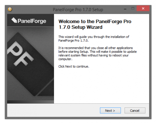
This tutorial assumes the prerequisite that the user's computer meets the System Requirements and have successfully completed the Installation of the PanelForge Application. Details on these subjects are covered elsewhere in the PanelForge Reference documentation.
When the PanelForge Application has been installed a 'shortcut' link is added to the Windows Start Menu/Screen. The PanelForge Application is opened via this 'shortcut' link. If the Application has not been previously opened then a window prompting the input of your valid PanelForge Serial Number will also be displayed.
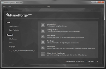
The PanelForge 'Welcome Window'
When first opening the PanelForge Application the 'Welcome Window' is displayed. This window provides simple access to load and create PanelForge Projects. The PanelForge main menu bar is also available as well as links to the online documentation.
In this case we will click the cursor on the 'New Project…' link to create a new PanelForge Project.
Creating a new PanelForge Project
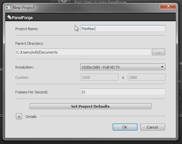
After the 'New Project…' link is pressed in the 'Welcome Window' the 'New Project' options window is displayed.
The minimal required input in this window is to enter the 'Project Name'. This will create a PanelForge Project directory with the specified name in the 'Parent Directory'. The PanelForge Project files will be stored here.
The location PanelForge Project directory (folder) can be quickly be adjusted by pressing the '…' button to the right of 'Parent Directory' field to display a directory selection window.
Other options are available in this window, although in this case the default options meet our needs. These options may need to be adjusted based on your client's requirements.
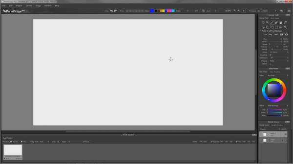
A Blank PanelForge Project
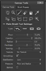
When a PanelForge Project is first created or opened the 'Canvas Workspace' is displayed. The 'Canvas Workspace' provides familiar 2D drawing and editing functionality. Much of this functionality is accessible via the Canvas Tools, Colour Picker and Canvas Layers palettes to the right of the Workspace.
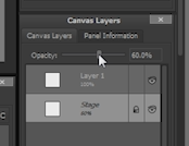
In the Canvas Layers Palette two layers are shown in a new blank PanelForge Panel. The 'Layer 1' layer is a normal editable canvas layer, but the 'Stage' layer is a special layer providing access the output of the 3D Stage element of a PanelForge Panel in the 2D Canvas.
Even though the 'Stage' layer is omnipresent in all PanelForge Panels its opacity and visibility can be adjusted. As in this case we plan to draw 2D overlays over the Stage output we will a select and reduce the 'Stage' layer opacity to '60%' as a quick way to diminish its intensity. This will make drawing over the 3D assets easier later on.
Switching to the third dimension
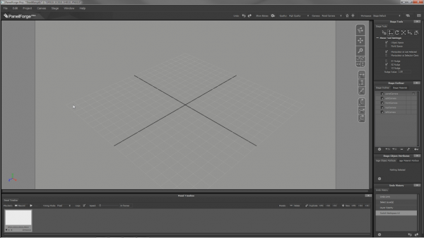
To work on the 3D element of the PanelForge Panel we switch to 'Stage' workspace. Switching Workspace is performed by selecting a Workspace in the 'Workspace' menu in the top right of the PanelForge Window. Alternatively the quick workspace switching button to the right can be pressed.
Similar to the Canvas Workspace Tools and options are shown in the Palettes to the right of the Workspace. We will be introducing the basic tools and concepts to quickly create our first 3D Stage environment.
Working with 3D Geometry Assets
A PanelForge Stage is built by populating it with Objects made of 3D geometry. The PanelForge Assets Palette window manages Asset files of Stage Objects allowing them to be quickly imported.
PanelForge comes with a built in Asset Library of 'Primitive' Objects. These objects range from simple shapes to characters and complex environments.
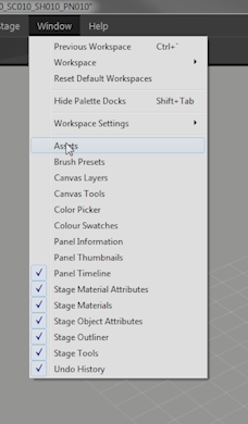
To show the 'Assets' Palette window select it from the PanelForge main 'Window' menu.
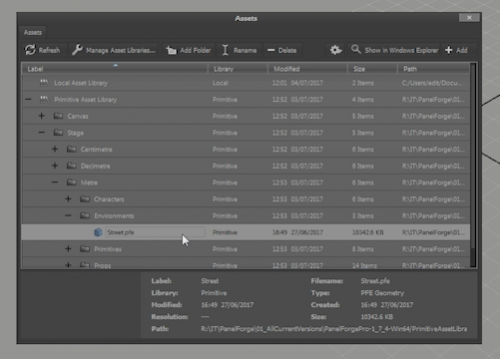
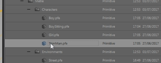
The 'Assets' window shows the hierarchy of files and folders in the available Asset libraries.
Clicking the cursor on the plus and minus icons to the left of asset list will expand and collapse the visible hierarchy. In this case we navigate to the 'Street' Stage environment asset in the Metre scale.
To add this Asset to our stage we can either simply drag the entry to the Stage Viewport, alternatively the 'Add' button in the top right of the 'Assets' Palette can be pressed.
In addition to the 'Street' environment we add the 'ThinMan' character into the Stage in the same manner.
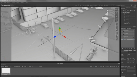
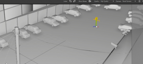
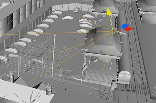
When Assets are added to the Stage they are placed in the centre of the Stage. The centre of the stage is identified by the grey and black grid. This grid is used as a guide and not visible in the stage output.
Positioning 3D Stage Objects
The currently selected object in the Stage is highlighted with an orange line or 'wireframe' overlay. Depending on the active Stage Tool a different interactive manipulator is displayed as Stage overlay.
In the case of the Stage 'Move' tool arrows are displayed which can be dragged with the cursor. As the manipulator is adjusted the Stage object is also similarly adjusted.
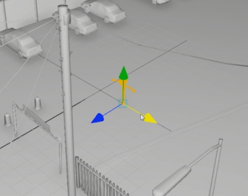
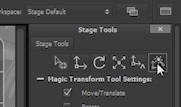
The 'Magic Transform' Stage tool provides a particularly intuitive but powerful method of moving Stage Objects. By moving and clicking the cursor over any surface in the Stage Viewport the selected object will be moved to the specified point on the surface.
In this case the 'ThinMan' character can be moved very quickly and precisely to any point in the car park/parking lot.
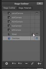
An outline list of all the objects present in the Stage is shown in the 'Stage Outliner' Palette. One function of this Palette is to select the current manipulable stage object from the list by clicking the mouse cursor. In this example we will toggle the lock object attribute by clicking in the first column to the right of the object entry. By 'locking' an item it will stop an object being accidently modified with any of the Stage Tools.
Using the Stage Cameras
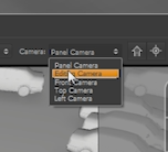
Within the 3D Stage two perspective Camera objects are available. Initially we have been viewing the Stage with the 'Panel Camera'. This Camera is also used to specify the output view of the PanelForge Stage.
We will switch to using the second 'Edit Camera' to give an overview of the stage without changing the output 'Panel Camera'. To switch the Camera used by the Stage Viewport we select the desired camera from the 'Camera' popup menu in the Workspace toolbar.
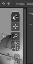
The 'Navigation Overlay' in the top right of the Stage viewport provides a quick and simple method to move the currently used Camera. Simply click and drag the cursor in one of the seven areas to perform different camera moves.
Like other objects in the Stage, Cameras can be selected and moved using the Stage Tools. Cameras are shown as simple line or 'wireframe' representations, this includes lines showing the camera's field of view. In this case we can move the 'Panel Camera' to our desired position.
Creating the Storyboard
The Panels that form the storyboard are shown in the Panel Timeline Palette at the bottom of the PanelForge Workspaces.
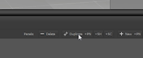
Until now we have just been using a single Panel but we can easily build a sequence of Panels by using the 'Duplicate +PN' button in the 'Panel Timeline'. This button will duplicate the currently selected Panel and increment the new Panel's numbering.
The new Panel can then be edited. In this case the 'ThinMan' Character will be moved. After we are happy with a Panel we can duplicate the current Panel and so on to for our Panel sequence.
For speed and clarity we have performed all the Stage Workspace work continually, but at any moment we can switch back to the Canvas workspace using the previously described 'Switch Workspace' button.
The Canvas Drawing Tools
Now back in the 2D Canvas Workspace you can see all of our 3D staging is available on our timeline represented as a layer called 'Stage'.
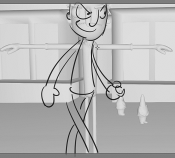
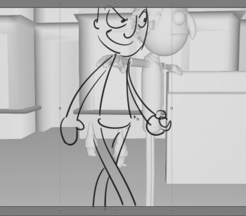
To use the Canvas 'Paint Brush' tool we can select the 'Layer 1' in the 'Canvas Layers' Palette and start adding more detailed expression to the character. Simply draw by click and dragging the cursor in the Canvas Viewport.
For speed a Layer can quickly be copied to any other Panel by dragging a Layer from the 'Canvas Layers' Palette to a Panel in the 'Panel Timeline' Palette.
In this example we copy the layer containing the 'ThinMan' drawing to the next Panel.
Switching to the next Panel we can then use the 'Free Transform' to quickly move the Layer to a desired position.
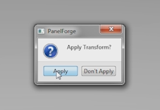
To finalise the free transform result double click the cursor inside the layer boundary. Alternately performing any other action in PanelForge will show the 'Apply Transform' confirmation window.
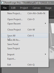
As we happy with the storyboard Panel sequence we save our work using the 'Save All' item in the main PanelForge 'File' menu.
Exporting the Storyboard
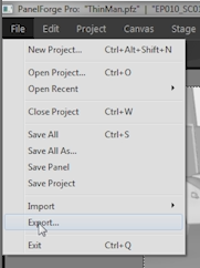
PanelForge provides a multitude of options to export the data created in a PanelForge Project. Accessing these features is done via the 'Export…' item in the PanelForge main 'File' menu.
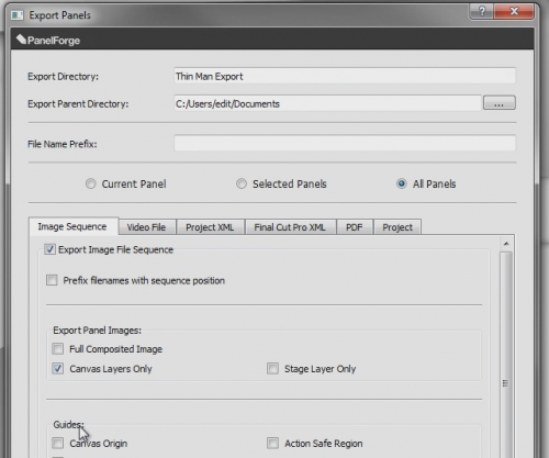
The 'Export Window' offers many file types to export to. Each export type can be activated and configured in the corresponding interface tab.
All the files created during the export will be saved in a new directory named with the contents of the 'Export Directory' field. This export directory is created in the 'Export Parent Directory' location, this field can quickly edited using the '…' button to display a directory selection dialog window.
If an export of the same type is made to the same location then the previous version will be overwritten.
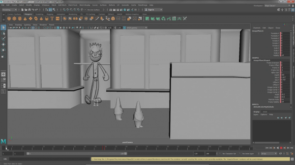
In this example we will activate the 'Export to Image File Sequence' option. The 'Canvas Layers Only' for use in the Maya Camera Image Plane overlays will be activated.
Also the 'Export Project XML File' option is activated. This exports a special file containing PanelForge data which can be used by the 'PanelForge Maya Tools' to reconstruct the PanelForge Project as an animated sequence in Maya.
Pressing the 'Save' button will perform the export, a progress bar will displayed during these calculations.
Importing into Maya
PanelForge provides very powerful but fast and easy to use tools to import the exported data from PanelForge into Maya.
The 'PanelForge Maya Tools' can be found by selecting the 'Show Maya Tools in Windows Explorer…' item in the main PanelForge 'Help' menu.
The 'panelForgeMaya201XPlugin.mll' Maya Plugin contains import/export functionality for the PanelForge geometry asset cache '.pfe' file format. This cache format is optimized for very fast loading and small file size when used with PanelForge. It is also required to import the geometry assets provided in the PanelForge 'Primitive' Asset Library. (PanelForge also supports importing standard geometry formats such as '3DS' and OBJ'). This Plugin file can be loaded with the Maya Plugin Manager Window.
The 'panelForgeMayaTools.py' Maya python script contains interfaces to import and construct Maya scenes from 'PanelForge Project XML' files. This file can be simply 'sourced' via the Maya script editor. When the script is sourced its functionality is easily accessible via the added 'PanelForge' main Maya menu. This PanelForge Maya Tools script can used out of the box or easily adjusted and integrated into an existing studio pipeline.
In this example we will select the 'Panels from PanelForge Project XML…' item from the 'Import' sub menu of the main 'PanelForge' Maya menu.
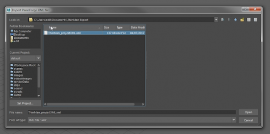
A file dialog window will be displayed to select the desired PanelForge Project XML file to import.
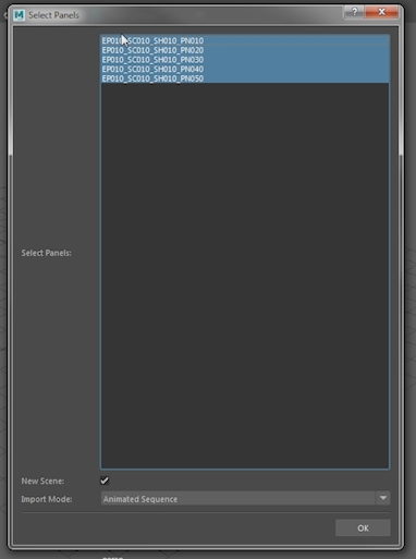
After the PanelForge Project XML file has been loaded the complete range of Panels is drag selected in the 'Select Panels' dialog window. The 'Import Mode' is kept to the default 'Animated Sequence' value.
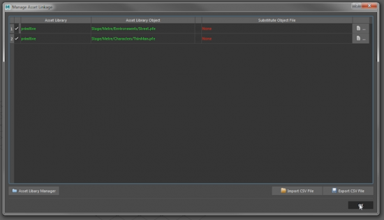
Next the 'Manage Asset Linkage' window is displayed. This window shows a list of all the geometry assets used in the Panels selected for import. These assets can be optional replaced with substitute geometry in other Maya compatible files. Any changes made here can be exported and Imported as 'CSV' settings files. In this case we have no need to make any changes and simply press the 'OK' button.
After a short interval tracked with a progress bar the animated scene will be constructed. If an 'Image Sequence' was exported into the same directory as the PanelForge Project XML file they will also be added as Camera Image Plane nodes. The timeline frame may need to be advanced for the displayed
